Project Lambda
This experimental project is about to automatically control the airgate of a
wood heater with the help of a temperature sensor, a micro controller
and a stepper motor.
If nobody is there to close the airgate when the fire has burnt
down, a lot of heat goes lost through the chimney. So it is nice
to have this done automatically.
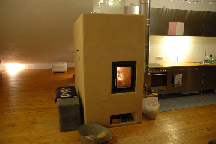
The natural loam masonry wood heater to be digitised
Please note that this really is an experimental project. I am not an experienced, professional electrical engineer, this was my first EE project. The circuit (schematic!) may have flaws, and regarding the software, I would probably do many things different by now.
Sensors
The only information needed to control the airgate of a wood heater is the temperature of the exhaust gas measured shortly after the firebox. The amount of residual oxygen is useful to determine the right mass of wood, and the temperature of the exhaust gas entering the chimney is interesting to get an idea about how much heat is absorbed by the oven.
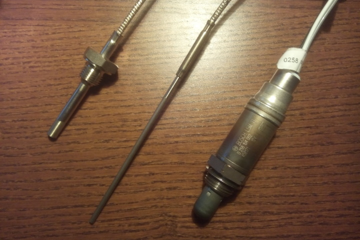
PT1000 (up to 400 °C) for measuring exhaust gas temperature shortly before the chimney, the type K thermocouple (up to 1200 °C) for exhaust gas temperature shortly after the firebox and the oxygen sensor (step change) Bosch LSM 11.
Installation
Shortly after the firebox by Brunner, a blind screw with M12 standard thread is located. This is an ideal place to install the type K thermocouple. The problem was however, that the clamping screw for the thermocouple was only available up to M10 or with different G threads. The solution was to turn off a G 1/4'' clamping screw and furnish it with a M12 thread.
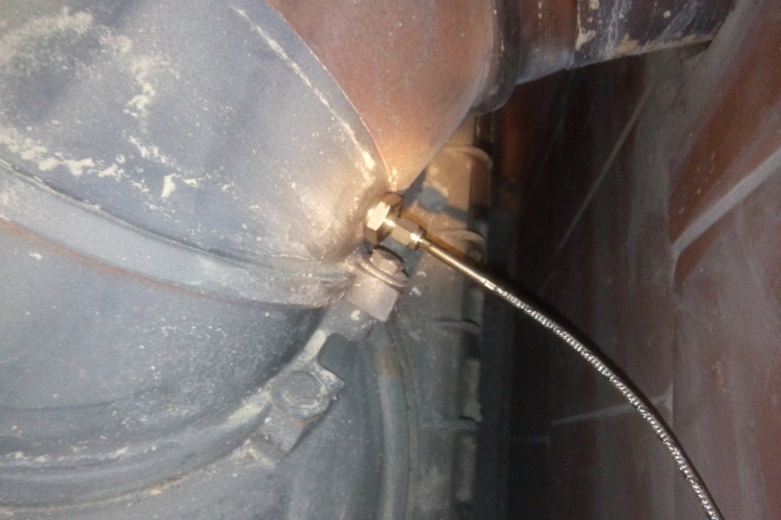
"Overburn" with installed type K thermocouple
The PT1000 resistance thermometer with G 1/4'' thread and the oxygen sensor with M18x1.5 fine thread were installed in the "cleaning door" in the last flue close to the chimney, furnished with the respective bore holes and threads.
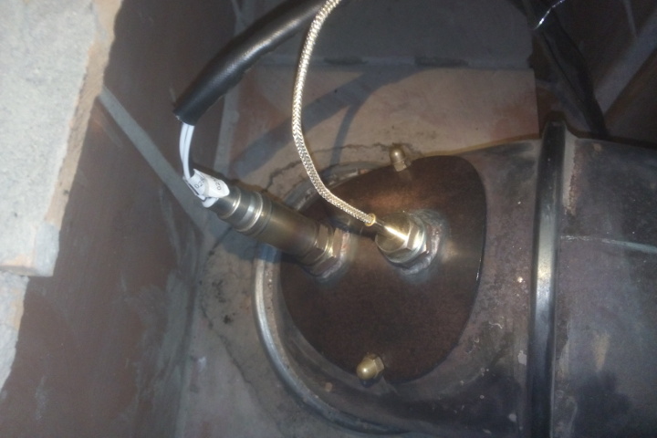
"Cleaning door" with installed oxygen sensor and PT1000 resistance thermometer
Evaluation
-
Type K thermocouple
The temperature measurement evaluation of the type K thermocouple is done comfortably with an AD8495 precision amplifier, already including cold junction compensation. The output voltage is 5 mV per °C, so the conversion is very simple, but due to non-linearity, the precision is accurate to max. +-2 °C deviation only in the range from -25 °C to 400 °C. Outside of that range, additional linearisation is necessary. The Application Note AN-1087 and the article Kaltstellenkompensation auf Basis Hardware und Software - ein Vergleich offer interesting information on that subject.
Without additional linearisation, the deviation is about 11 °C at 1000 °C, that should be accurate enough for now.
The circuit was built according to the "Basic Connection" in the data sheet of the AD8495, with 5 V single supply and no reference voltage the measuring range is about 3 °C to 990 °C. -
PT1000 resistance thermometer
For the resistance thermometer, a combination of Wheatstone bridge and non-inverting operational amplifier with offset carries out the evaluation.
With an LM358, whose max. output voltage is 3.5 V at 5 V supply, this gives a measuring range from -40 °C to almost 380 °C.
Linearisation of the PT1000 and the Wheatstone bridge is done with a simple lookup table and linear interpolation in the program. This resulted in a very satisfying consistency with the measurements of the type K thermocouple (and different other thermometers). -
Oxygen sensor
In the interesting range for a wood fire of Lambda 1.0 to 2.0, the oxygen sensor Bosch LSM 11 delivers a voltage of about 400 mV to 4 mV, which is amplified by factor 11 with an AD8551 precision operational amplifier. Since the AD8551 offers real rail to rail output voltage, the measuring range is more than enough for Lambda 1.0 to 2.0.
The heating of the sensor is supplied by a 12 V 10 A switching power supply.
Interference, Noise, Resolution
High frequency interference is suppressed by RC low-pass filters at the sensor
inputs, and for noise cancelling the CPU of the ATmega328P is set to sleep during
ADC conversion and woken up again with an ADC interrupt when conversion is done.
Additionally to 16x oversampling, an exponential weighted moving average is calculated.
This results in accurate and stable measurements.
Adding a 50/60 Hz low-pass filter in front of the ADC inputs can efficiently
help against noise pulled in by long, unbalanced sensor cables but were not necessary.
It is also worth noting that according to Atmel AVR126, AVCC of the controller
should be connected to VCC via an LC network (10 uH, 100 uF) to prevent digital noise
from entering the ADC.
Also interesting to know is that ADC input channel 5 and 4 of the ATmega 8 family use digital power,
while ADC input channels 3-0 use analog power:
ATmega ADC input channel analog vs digital power
Testing temperature measurement in the oven
Probably not being a very scientific but fun testing method, a temperature measurement test run in the oven was unavoidable.
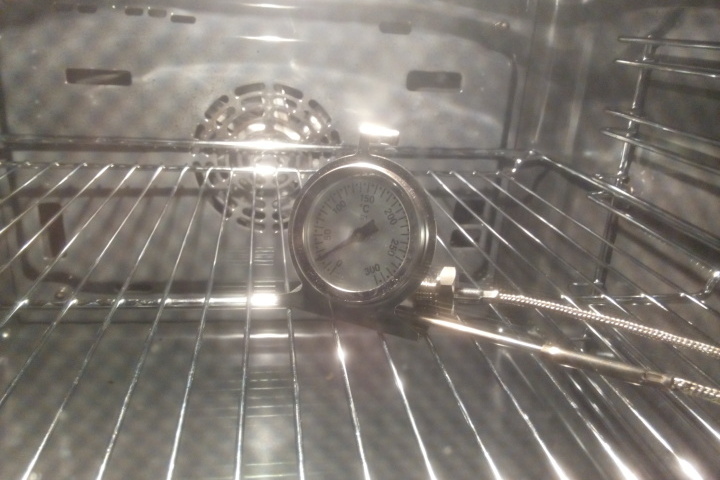
Temperature sensors about to be crisped
The temperature of the oven was increased in steps of 50 °C from 23 °C to 284 °C. The thermostat of the oven by Siemens proved to be surprisingly accurate and set the oven exactly to the chosen temperature.
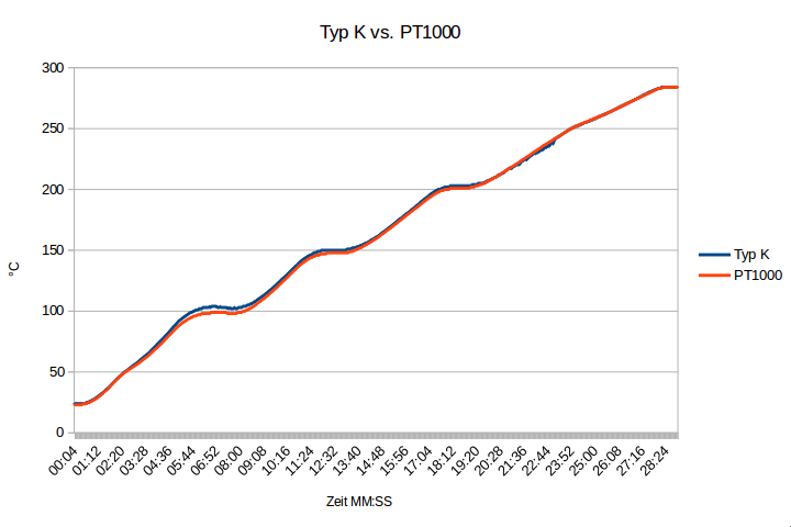
Probably because of the higher mass caused by the thread with hexagon, the PT1000 seems to be slightly inert compared to the type K, which became very obvious when cooling off where the PT1000 was up to 30 °C behind the type K.
Oxygen Sensor Heater Control
The 12 V PTC heater element of the oxygen sensor is switched on and off by a 10 A relay, which is driven by a 2N7000 MOSFET controlled by the AVR. A 0.1 Ohm/9 W shunt resistor is used to measure the current "drawn" by the heater, allowing to detect when it has reached steady state, where its internal resistance is about 10 Ohm and the current about 1.25 A. It also allows to detect faults such as connection or power supply failure (0 A current) and short circuit: above 7.5 A the relay is switched off by firmware and if that should fail for some reason there is an 8 A fuse providing additional protection.
Airgate Control
The airgate is controlled by a 1 A stepper motor driven by a DRV8825, offering features
like microstepping and current control, and a simple STEP/DIR interface.
Ironically, the cheapest way to get a DRV8825 would have been, at least for me,
a ready to use breakout board - but since I don't want to just plug things together,
I ordered a DRV8825 for the price of two such breakout boards, plus the nice
SSOP to DIP adapter from Sparkfun.
A stripe of aluminium foil with a tiny amount of heat sink paste provides
some cooling for the PowerPAD package - not sure how good that works, but with
the motor current rated 1 A it doesn't seem to get too hot without additional cooling.
It also wasn't so easy to get some relatively small 100 or 200 mOhm resistors,
so I used two 100 mOhm SMD ones desoldered from some broken board.
The program implements a simple linear acceleration profile and reduces
the current significantly when the motor is standing still, hopefully just
enough to maintain its position with a minimum of power dissipation. When the
burndown is completed, the driver is put in sleep mode reducing power
consumption to almost nothing.
What is still missing is the mechanics, so the motor is actually able
to move the airgate...
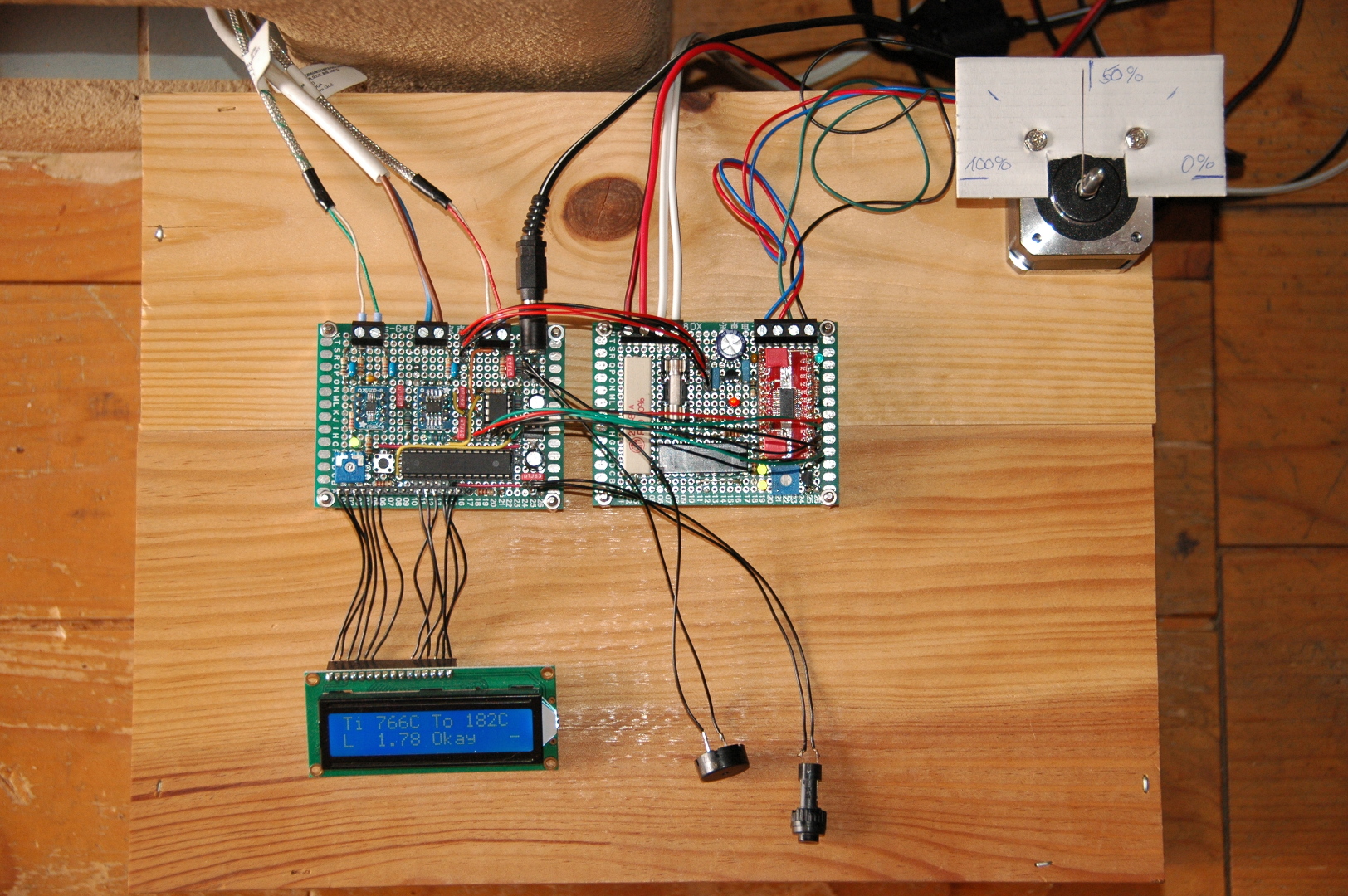
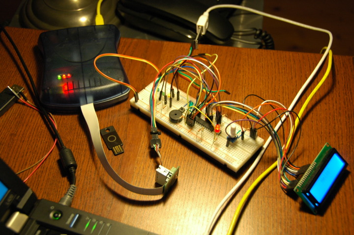
Complete circuit with stepper motor but missing mechanics to actually control the airgate
AVR, unit tests and Jenkins
To have unit tests and continuous integration is not as easy as with for example
Java and Maven, but almost - at least if one can live without coverage reports
and not being able to simply run the tests from Eclipse.
There are several unit testing frameworks suitable for an AVR project, some
of them optimized for embedded, but I felt like building my own little framework
AVRJUnit,
which creates a JUnit compatible report that can be evaluated by Jenkins.
The principle is to create a separate project for the unit tests
referencing the main project. The test project is uploaded to the
controller and the tests are run on-chip. The JUnit-compatible report
is sent via USART to the PC and written to a file.
The "Execute shell" build of the Jenkins job executes a simple shell script to build the test project,
uploads it to the controller and writes the test report sent via USART to the file
test-reports/tests.xml:
cd lambda-test
make clean
make
make flash
mkdir -p test-reports
(stty -F /dev/ttyUSB0 speed 9600 sane -echo; cat > test-reports/tests.xml) < /dev/ttyUSB0
Adding "Publish JUnit test result report" in "Post-build actions" creates a regular "Test Result Trend".
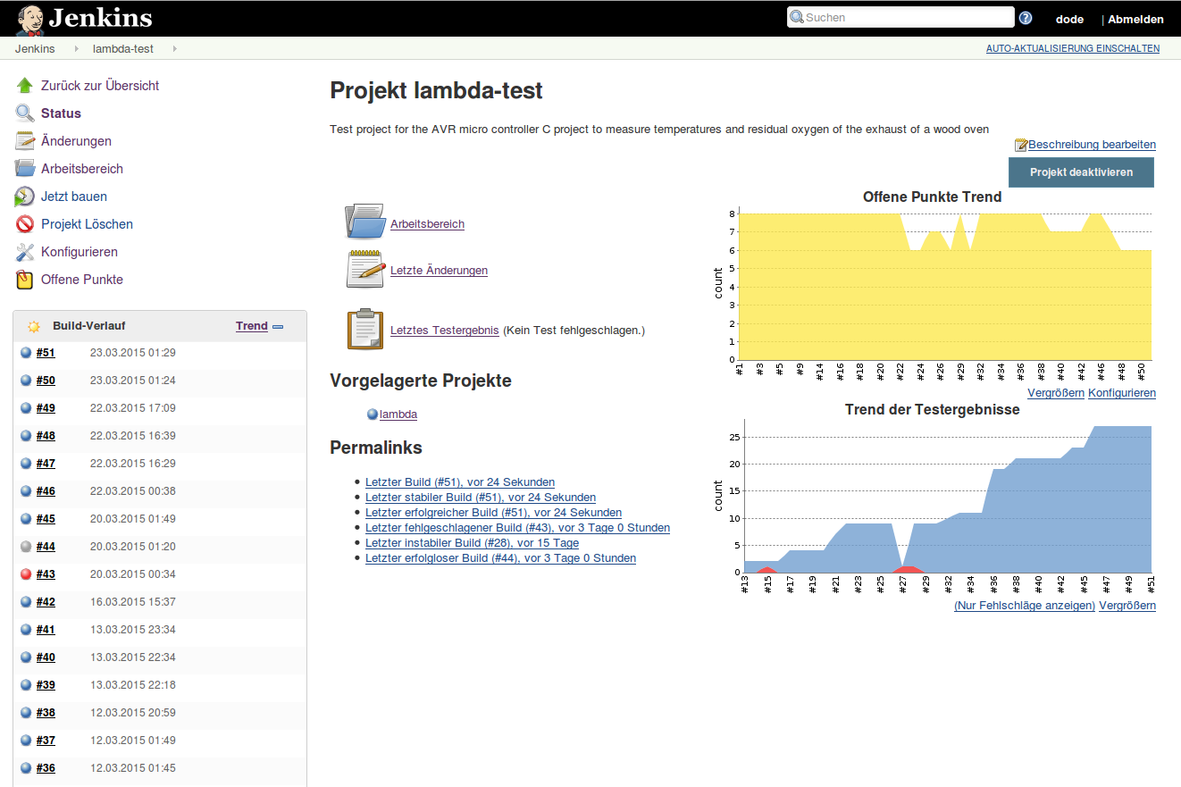
AVR test project in Jenkins
(click to enlarge)
Debugging
See AVR Debugging on Linux (with debugWire).
Unit testing and debugging setup
Burndown
Below a graph of the measurements recorded during burndown of about 12 kg
mixed briquet. The burndown is interesting because for a period of time,
the combustion was unusually rich - below Lambda 1.1. During that time quite
some grime developed in the firebox and as soon as the Lambda value went above
1.2 again, the grime disappeared pretty quick.
The ratio between both temperatures is very good, and it seems safe to say that most
of the heat is absorbed by the oven instead of being blown out through the chimney.
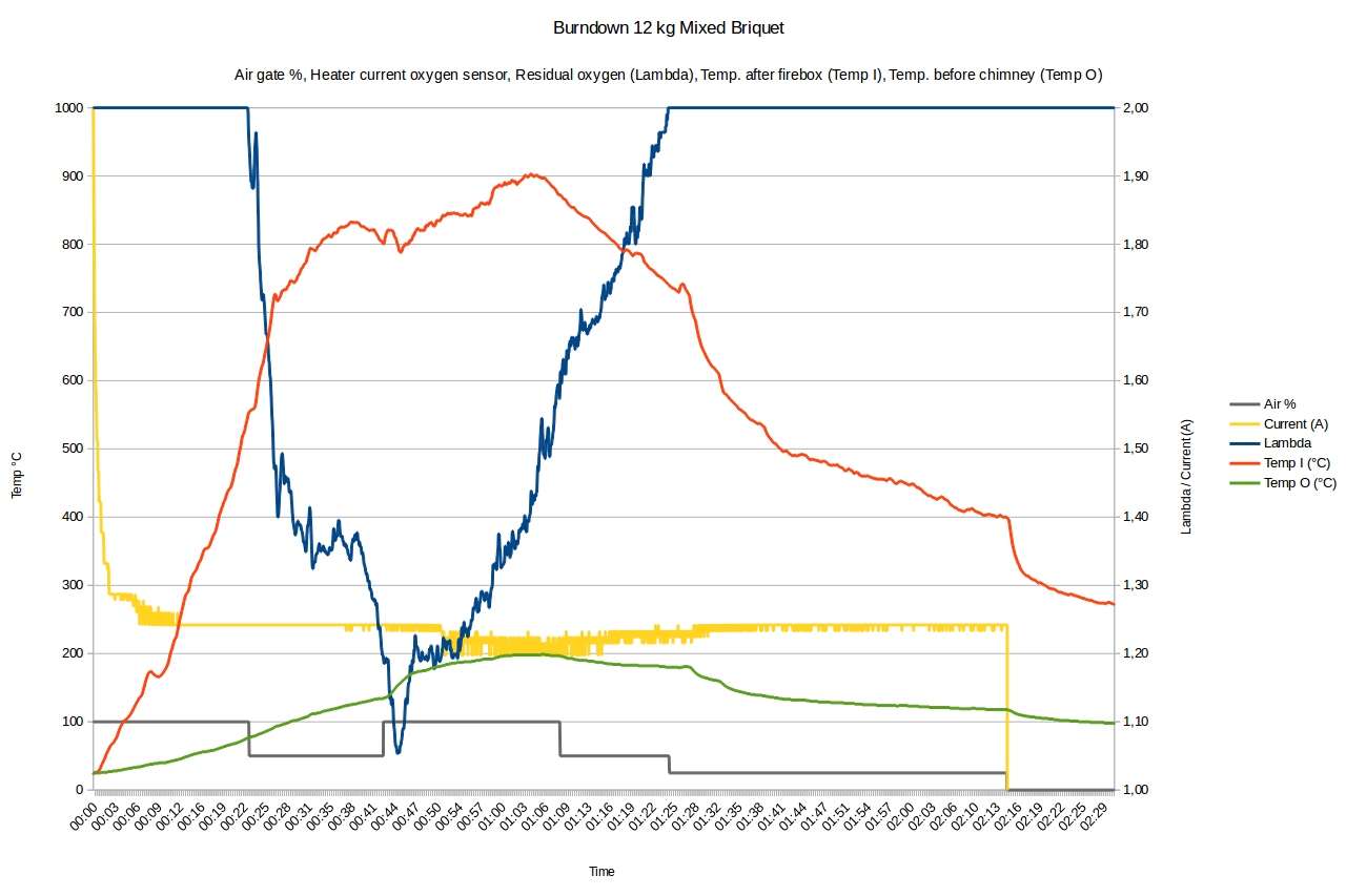
Measurements taken while burning down 12 kg of wood briquets
(click to enlarge)
Influencing Residual Oxygen
Most significant impact on the residual oxygen appears to have the mass of wood.
With this oven, about 10 to 12 kg of mixed briquet seems to be ideal as the Lambda
value rarely goes below 1.2.
With 15 kg (more hardly fits in the firebox), the composition becomes way
too rich, the Lambda value can be below 1.3 for a longer period of time and
even reach the lower end of the measuring range of 1.0. Under such conditions,
quite some grime develops in the firebox and a fully opened air gate valve lets
the temperature go up, but contributes only little to a leaner composition.
My conclusion: A wood fire is not easy to control and the right mass
of wood especially matters!
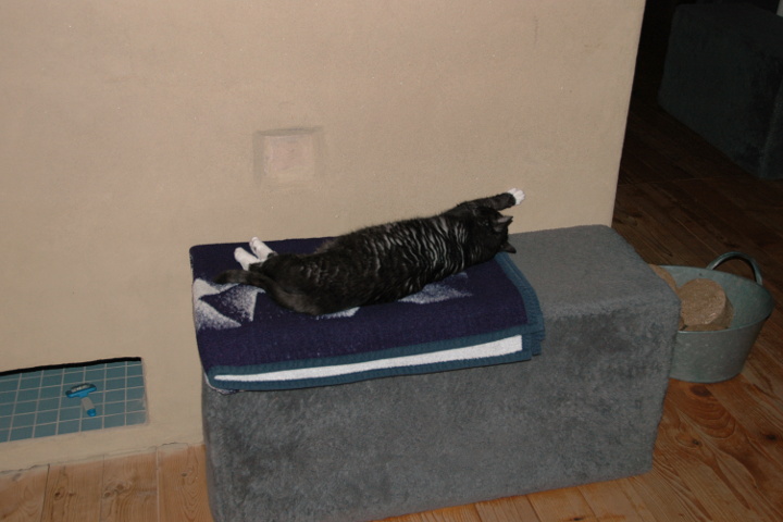
Linus is satisfied with the temperature of the oven
Additional Functions
The circuit and the program have a few more features on top of displaying measured values and controlling the airgate:
- Issue alerts at certain operation conditions
- Cycle through display modes with a pushbutton
- Run commands sent via USART (i.e. enable/disable logging)
- Run a fast motion simulation of a burndown by sending previously logged measurements via USART, to test rules for issuing alerts at certain operation conditions
TODO
- Mechanics for the airgate control
- Install and evaluate a door switch to know when the door is opened
- Build a nice case for the circuit
- Professional wiring and installation
- Improve and simplify the rather experimental firmware
- Recreate (and verify!) schematic with KiCad
Schematic
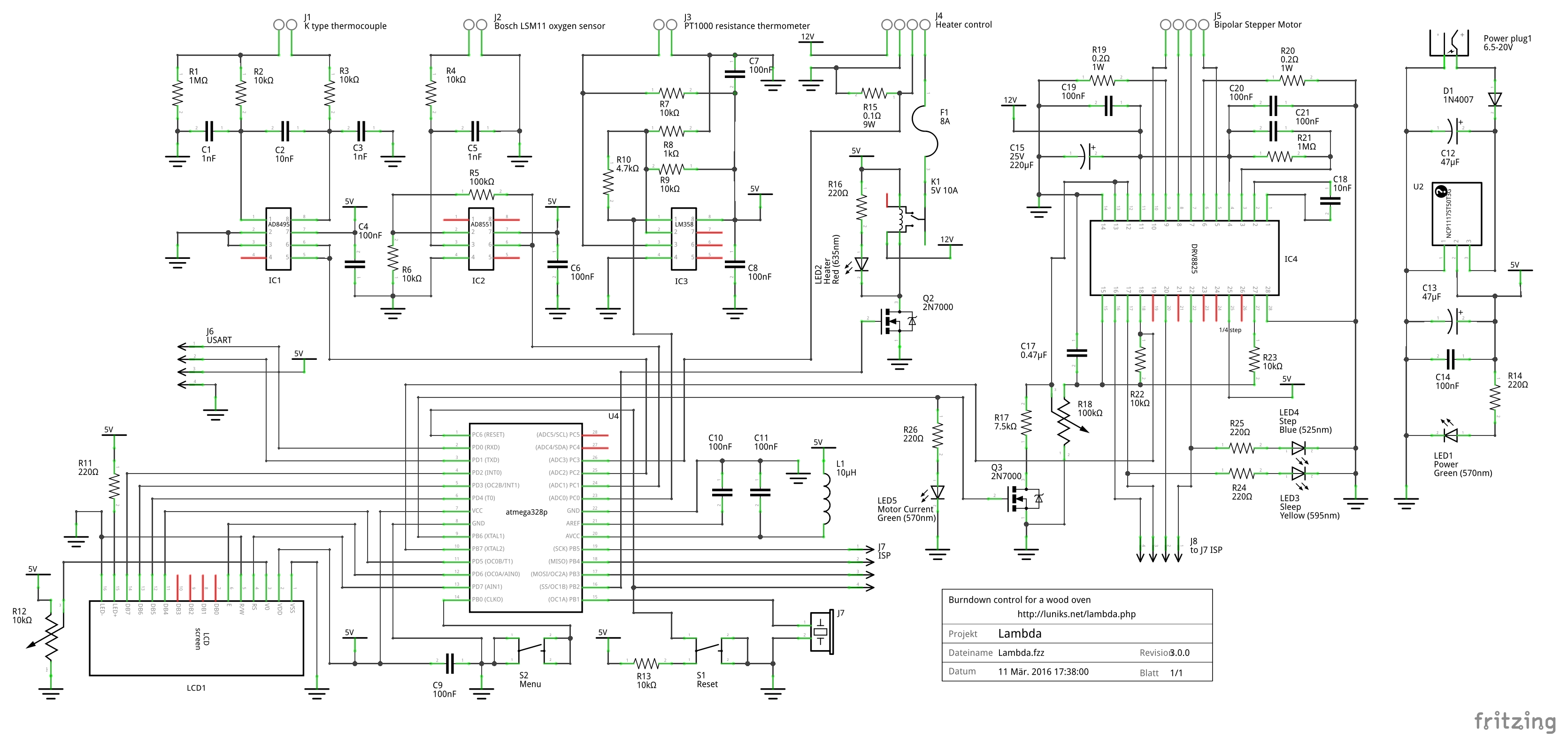
Schematic
(click to enlarge)
Circuits
- Evaluation type K thermocouple: Datasheet of the AD8495, "BASIC CONNECTION", page 14
- Evaluation PT1000 resistance thermometer with an LM358: Bridge circuit
- Evaluation Bosch LSM 11 oxygen sensor with an AD8551: Non-inverting amplifier
- Power supply: Arduino Uno Rev3
- Display: LCD Ansteuerung
Source Code
Attribution
- Makefile: AVR Programming
- Module lcdroutines: LCD Ansteuerung
Comments? dode@luniks.net